
Procedures
Here's a step-by-step guide on how the project was implemented.
First of all, we need to pair the devices. To do this, we must first connect the Bluetooth module in gateway mode.
Remove the microcontroller in the Arduino as shown. Be careful not to damage the microcontroller during the process. We recommend using tweezers to prevent the pins from getting bent.


Make sure that the jumpers (circled red) are set to USB position, so that we could send commands directly to the module.
By using gateway mode, we can send/receive AT commands directly from our PC to the Bluetooth module.
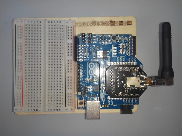
Assemble the Bluetooth module, Xbee shield and the Arduino as shown.
When done, connect the Arduino to PC via USB.
Finally, open TeraTerm after the above.

Before we proceed, let us note some of the pitfalls that you might encounter.
First, you might not see anything as you type, since sometimes echo is set to off. To fix this, go to Set-up -> Terminal -> Local Echo.
Second, responses might not be visible, so chose CR+LF on the transmit and receive on the same menu
Next, we need to configure the serial connection. Choose a 115200 bps (baud rate), 8 data bits, 1 stop bit, no parity, no flow control, one stop bit, and an appropriate port.
We are now ready to send AT commands. Send a AT+JDDS=0 to discover devices. If this doesn't work, we found it helpful to send a AT+JRES command to reset the module.
The response to this would be a list of bluetooth devices close to our bluetooth module.
We them send a command AT+JSDS=<MAC>,1101 so that we could pair the devices.


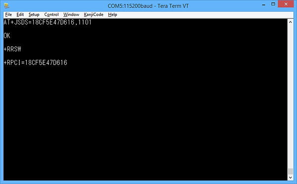

You might encounter an error like shown. Just keep trying until you connect to the device. By default, there should be no password set.
Then, upload this code to the arduino with the microcontroller inserted:
int led = 13;
int val = -1;
float temp;
int tempPin = 0;
void setup(){
delay(2000);
Serial.begin(115200);
delay(2000);
Serial.print("AT+JSEC=1,1,1,04,1111\r\n");
delay(2000);
Serial.print("AT+JDIS=3\r\n");
delay(2000);
Serial.print("AT+JRLS=1101,11,Serial Port,01,000000\r\n");
delay(2000);
Serial.print("AT+JAAC=1\r\n");
delay(2000);
pinMode(led, OUTPUT);
digitalWrite(led,HIGH);
Serial.flush();
val = Serial.read();
while (val != 'R'){
val = Serial.read();
}
delay(1000);
Serial.print("AT+JSCR\r\n");
}
void loop(void) {
if (Serial.available()) {
byte c = Serial.read ();
if (c == 'm') {
temp = analogRead(tempPin);
temp = temp * 0.48828125;
Serial.print(temp);
Serial.print("*C");
Serial.println();
}
}
}
Save this with a .py extension like temp.py for example and double click it:
import time
import serial
from Tkinter import *
# Serial port settings
serial_speed = 115200
serial_port = 'COM3'
ser = serial.Serial(serial_port, serial_speed, timeout=1)
# Main
class Application(Frame):
# Measure
def measure(self):
# Request data
ser.write("m")
data = ser.readline()
# process & display data
if (data != ""):
processed_data = data.split(",")
self.temp_data.set("Temperature: " + str(processed_data[0]))
self.temperature.pack()
# loop
self.after(1000,self.measure)
def createWidgets(self):
self.temperature = Label(self, textvariable=self.temp_data, font=('Verdana', 40, 'bold'))
self.temp_data.set("Temperature")
self.temperature.pack()
# Init
def __init__(self, master=None):
Frame.__init__(self, master)
self.temp_data = StringVar()
self.createWidgets()
self.pack()
self.measure()
# Create and run the GUI
root = Tk()
app = Application(master=root)
app.mainloop()
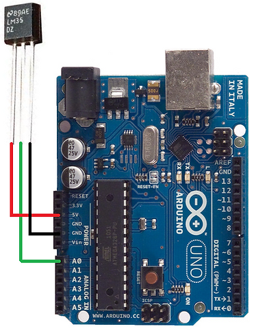
Connect the LM35 to the Arduino board's 5V supply and ground, with its output pin connected to the GPIO port labelled A0 on the arduino board.
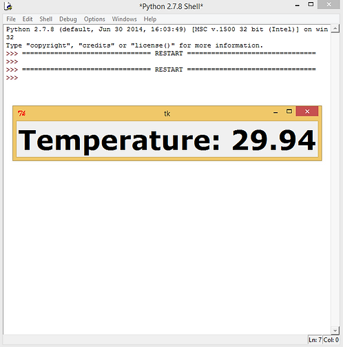
Finally, run the python program using IDLE or just by double clicking it and you should see something like this. It should update the temperature value every 1 second.